Geometric dimensioning along with tolerance is a language that consists of standard design and symbols which is most pronounced by manufacturers and engineers to explain a product to communicate with each other to produce something.
If you have sufficient knowledge about the creation of a well-structured GD&T in the engineered drawing, you can improve your machine communication and ensure that anyone in the group can speak and understand the language.
GD&T Symbols
When people are geared about GD&T what comes to their mind is GD&T symbols. Almost fourteen GD&T characteristics are present and are shown with different symbols and below is the GD & T symbols chart.
All symbols explain the type of tolerance that is required for a feature control frame. The characteristics are bound together according to tolerance types like orientation, location, form, runout, and location of derived media points.
The most interesting benefit of GD & T is that it explains the design intent rather than the resulting geometry. Unlike a vector is not an actual object but in representative form. If you described product geometry that is related to intended functionality along with the manufacturing approach it is quite simpler than to explain everything in linear dimensions. It also offers work as a communication tool between customers, vendors as well as with quality inspectors.
How GD&T Works
Engineering drawings show the all dimensions and features of a part. One step ahead of the tolerance values required to be specified with maximum and minimum acceptable limits.
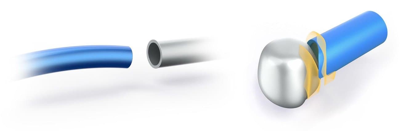
Similarly, a cylinder having tolerated diameter will not fit its hole if the cylinder got bent during the manufacturing process as it needs straightness control that is quite difficult to communicate with plus-minus Tolerancing. Tolerance means the right variation of all design features in terms of product maximization approval limit in the manufacturing process and depends on the functional as well as visual purpose parts.
Moreover, tolerance stacks up as well. Like, if you create a chain link where each Shaft has a 0.1 mm negative tolerance and each hole with a 0.1 mm positive tolerance, ultimately you will receive at 100 links of a 20 mm length difference. This standard is not only for developers and engineers but also for quality inspectors to measure the dimensions and tolerance. For tolerance practice, there are certain tools used:
- digital micrometers
- height gauges
- Clippers
- Dial indicators
- Surface plates
- Coordinate measuring machine
GD&T Symbols Tolerancing Guidelines
An engineering drawing should deliver a product that has no complexities and restrictions. Earlier manufacturing was specified by X-Y areas. For instance, when you drill into a hole, the hole should be within the range of X-Y areas. If the hole was not within the range of the X-Y area then it fell in a circumscribed circle. Currently, GD&T is defined by the American Society of Mechanical Engineers and separated from the rest of the world by ISO 1101-2017. In this regard, we compile some guidelines to follow…
Clarity of Drawing
Clarity is the most important factor of drawing even more than completeness and accuracy. To increase clarity, draw dimensions along with tolerance stay side of the boundary of the parts and are applied in true profiles, deliver all the function of parts, stagger and group dimensions along with white space.
Cost Down
To keep costs down you should always design the loosest feasible tolerance. And when you have assumed the 90-degree angle don’t specify it. Because all the dimensions and tolerance are valid at 20 °C / 101.3 kPa until stated otherwise.
Leave GD&T Work
Always use a general tolerance at the bottom for all dimensions. The tighter and looser tolerance shown in the drawing will surely supersede the general tolerance. Now, observe tolerance functional features along with their interrelations first, and move on to the rest parts. That is the reason always leave the work for developers and manufacturing experts and avoid explaining the manufacturing process in the drawing
Conclusion
GD&T is a purely new way to describe tolerance and dimensions as compared to traditional tolerance. If GD&T is used properly it will not only improve the quality but also reduce the cost and time by offering a common language and communication for expressing design intent.